You know you have a problem with OCD when …
on the P38 camper conversion, the spec requires locking differentials with an air compressor of the ARB style,
not wanting to stick the big ARB/Carling type switches in the dash panel like this
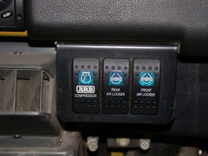
or even like this
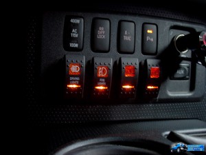
so I decided that I would look into converting the OEM range rover switch that was no longer needed as we now have good old coil springs fitted.
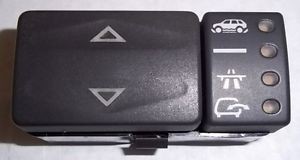
now this switch is not just any old switch it is an electronic communication switch that talks to the BECM, so som mods had to be done,
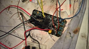
A quick look inside and the wiring diagram showed promise
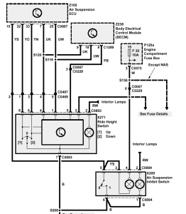
The buttons that are pressed by the rocker switch come out on pins 8 & 6, the button illumination is standard, so just need to control the LEDS.
the Idea is that the rocker switch will select what is on/off of the Air compressor/ rear diff lock or front diff lock, and also give an indication that the compressor is working via a simple feedback.
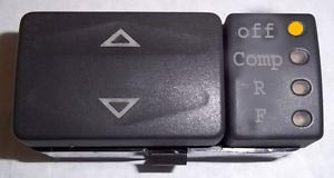
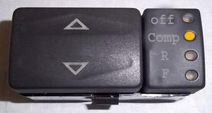
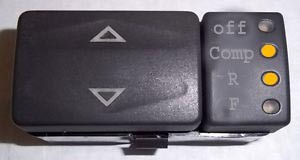
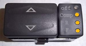
at any point when the compressor is ON and the tank pressure switch clicks in to engage the pump the Compressor LED will flash, this lets the driver know the compressor is working, over the years in Dakar the noise in the car and wearing helmets means its not possible to hear the compressor run, if a pipe to any diff fails the compressor runs constantly and burns out, result = no diffs locked = stuck or a bust diff, so this feature is really important for reliability.
so how does it work, I used a PIC16f628 microchip and a ULN2003a darlington transistor array, cut the track to the LEDs , soldered them inside the OE switch case and knocked some code up and in one night I had an Air locker diff control module that is OEM looking and fits perfect, and also easy to bodge/bi pass in the event of failure, which will never happen will it 🙂
Update Apr 2020
I also made a cover so the legends on the lights were correct.Version 1 wasnt a success, the cover is small and the detail was poor, I also thought that by making the cover that was over the led’s thin then they would shine through, but they didn’t so version two has now been designed and ordered from shapeways.com.
I will add another update when it does/does not work.
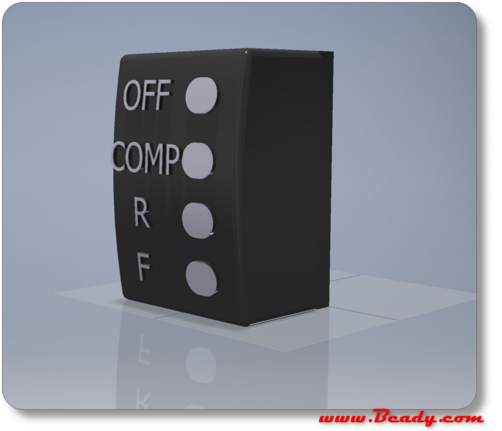
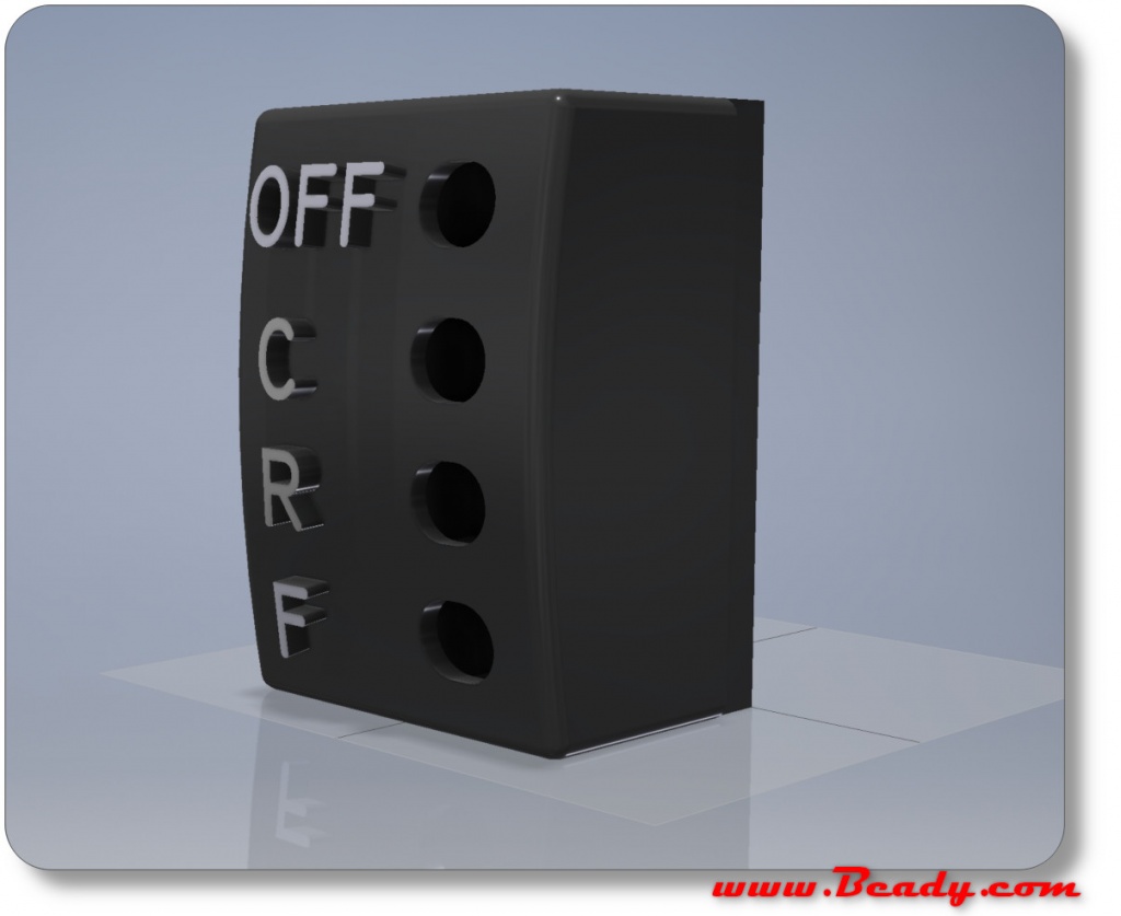
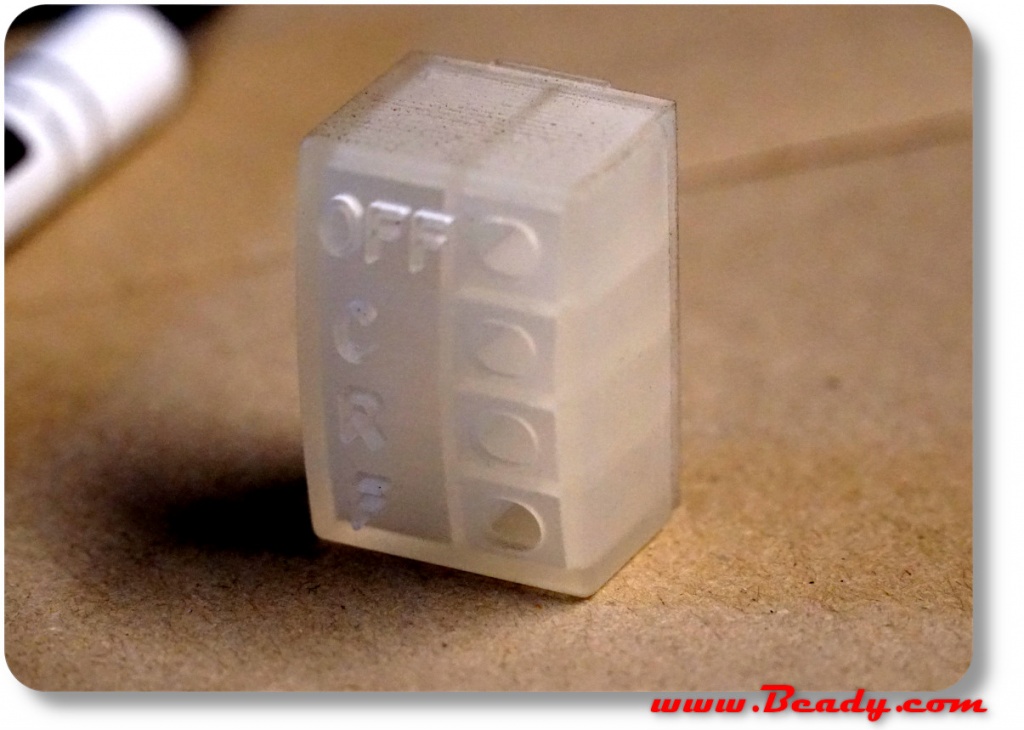
after recieving the V2 switch cover in translucent smooth plastic with holes for the LEDs , I noticed that the OEM has push out lenses for the LEDs, so I have modelled the V3 version to take them, oh well, ony cost 24£ to get to here 😉
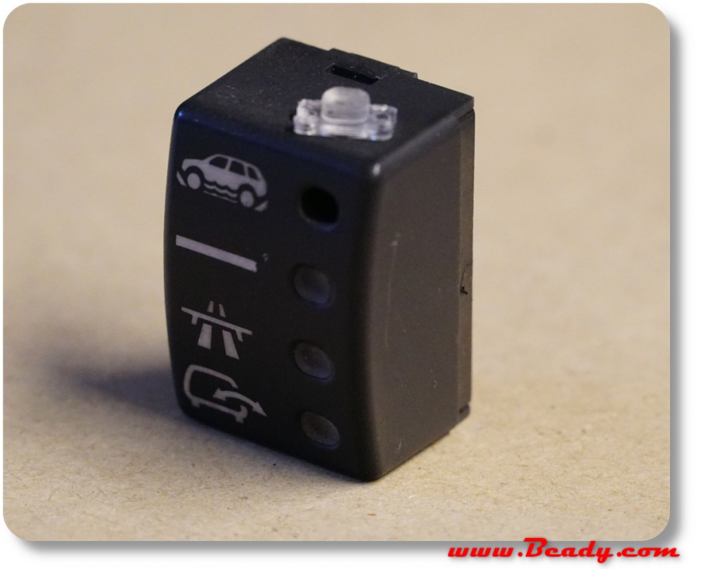
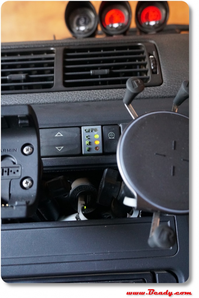
So the idea to use translucent body and paint the cover worked, the dash illumination comes through nicely, i dint have the correct grey which didnt matter I will have for the Mk3 version.
Hi Mr Beady
Can ask you if you can explain me more about this little great idea
Thanks
what do you want to know?
I simply cut the tracks to the existing circuit and used the two switches (up/down) into a pic chip, then a ULN2003 to relay the control to three normal relays.
it is tight getting the circuit inside the original housing but worth it, the trick is to use very thin wire for the interconnects.
bd
Thank you for the reply
I would like to have one like that but honestly i dont know nothing of electronics i would have to ask a person that knows to make one for me and thats why im asking you some help so i could try and tell if asked how it was build
Or by any chance if you could build one for me and just let me know how much you want for it it would be even better
Thanks
the circuit is simple , but if you have now electronics experience then it would be a bit harder but a good place to learn , maybe it would be a COVID lockdown project
unfortunately, I way too busy with work to make another, although I have revisited it and looked at the design, it may be easier to make an original switch work with an adapter plug in box
now I have a standard p38 to test I could look at the signals that operate the lights and make a cheap a little Arduino version.
come back to this post every so often I will update it if I get chance.