P38 BECM communications (Updated Mar 2025)
When making my p38 camper I needed to make a new wiring loom but still wanted to keep the look of the P38 internally as I feel it is a very tidy interior, I also wanted to remove the BECM and make a small neater one that did the bits I just needed.
The BECM talks to all the other systems (ABS,ENGINE,HVAC) via simple wires going hi and lo to indicate errors or status,
The outstations in the doors, display and the switch panel use a form of serial comms to talk to each other.
I only reverse-engineered the display but the comms system is the same on the others it will take someone else to sniff the codes using a simple cheap Arduino.
There is a working arduino sketch at the end of the post.
you just need three wires to the display, +12v and ground to make it work with any of the components., if you only want to listen then you can just sniff the data wire, to know which is sending the data is a little harder to do, because you cant detect which end pulled the line low.
The system runs on three wires,
- Clock wire
- Data Direction
- Data wire
- ground is always needed 🙂
The data wires to the display are easy to get to on the BECM they are on the plug just below the fusebox and can easy be identified because of the dual coloured wires. push a paperclip into the data wire and connect that to the a input pin on the arduino with a 1k resistor in series then connect a earth from the car to your arduino and then make a sketch to relay, use 4800 8N1 bps comms on the BECM wire to the serial monitor on the computer. then press things or make things happen on the car and see what gets sent to/from the BECM. you should see the mileage being sent from the display to the BECM it is easy to work it out.
Bytes : A6 13 83 73 45
A6 is the code to says its mileage then the mileage is in plain text here the mileage is 138373 (45 is the checksum)
Here is how the connections are wired into the switch panel for the windows
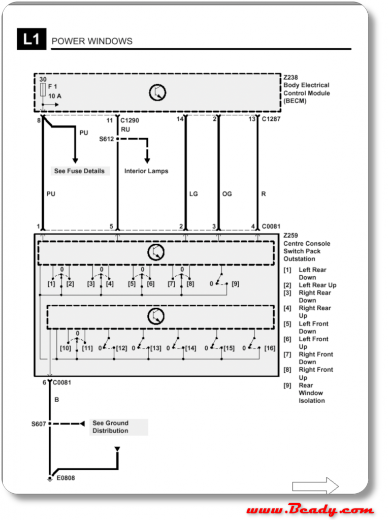
three wires OG,LG and R (black = GND)
on the display the signals wires are doubled up for reliabilty .
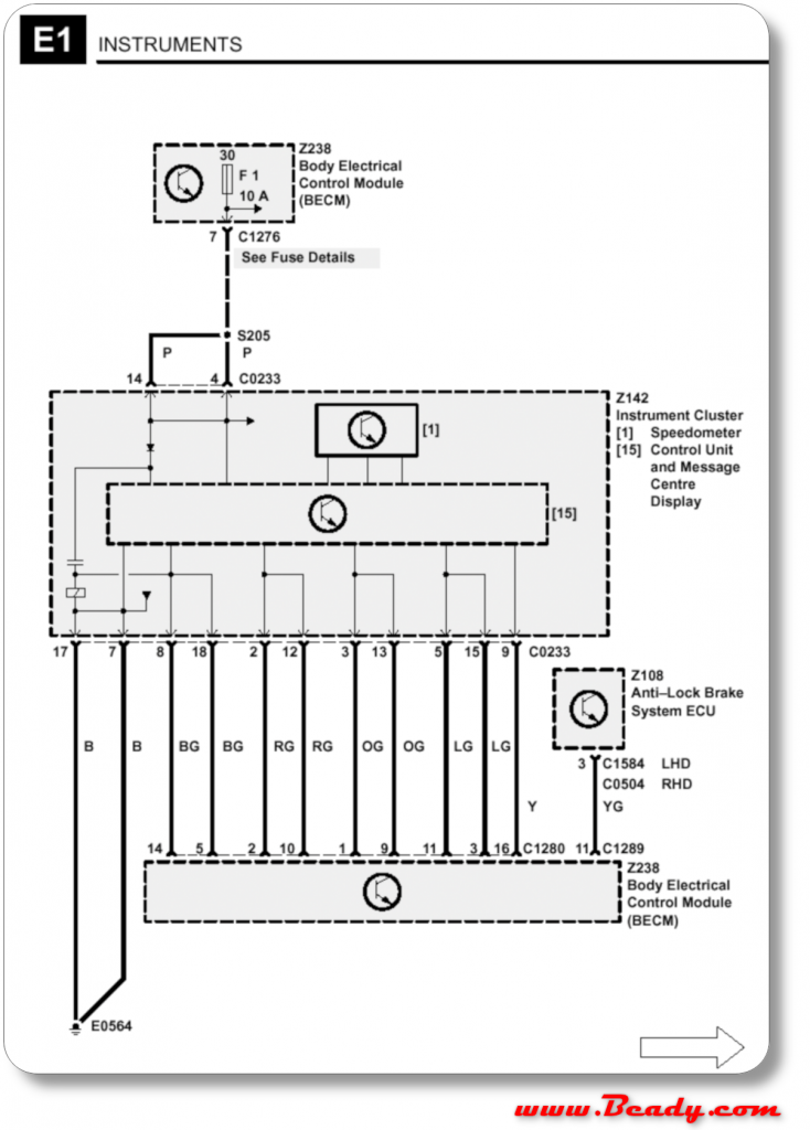
basically there is a red a green and a orange wire 2 & 12 ,3 & 13 , 5 & 15
orange is Data direction
red is clock signal
green is the actual data
the clock wire runs at 4.8 khz
the data dir wire is pulled low when sending data, you must wait 5ms before writing to the data line after pulling this low
and the data is 4800 8N1 just like any rs232
So what does this data ?
The data is in 10 byte blocks
which consist of two 5 byte sections
byte 0 : ID
byte 1 : data
byte 2 :data
byte 3 :data
byte 4 : Checksum byte : bytes 0,1,2,3 all XORed together
The display sleeps if it doesn’t get a valid data stream, so if you have power and nothing is on the screen then your data stream is wrong somehow.
to keep the screen awake when you dont need to send any data then you must send AA AA AA AA cs 00 which is the keep alive signal
Byte 1 is the control/action code
- 0xA5 : is the lights on the display
- 0x00 : are messageson the upper line of the LCD, I pressume these vary by Display ROM, you can set the language
- 0x0F : message on the lower line of the LCD
0x
OK, if you now used my Arduino sketch and have the hazard lights on the display going on/off what else can you send to the display?
Here is what I have found that you can send the display, I didn’t decode the data coming from the display because I didn’t need it.
| Byte # | Hex | bit | Function |
| 1 | A5 | {lighting } | |
| 2 | …. …0 | Left indicator | |
| …. ..1. | Main beam indicator | ||
| …. .2.. | Right indicator | ||
| …. 3… | Brake warning light | ||
| …4 …. | Low fuel light | ||
| ..5. …. | Over temp light | ||
| .6.. …. | Traction control light | ||
| 7… …. | Seat belt light | ||
| 3 | …. …0 | BATT light | |
| …. ..1. | Oil light | ||
| …. .2.. | ABS light | ||
| …. 3… | Heater plugs light | ||
| …4 …. | Engine check light | ||
| ..5. …. | Nothing ??? | ||
| .6.. …. | Transfer box warning | ||
| 7… …. | Trailer light | ||
| 4 | …. …0 | ||
| …. ..1. | SRS light? Gauges ON must be set to make gauges work I.e. BYTE 4 must be at least 0x06 for back light to be on and the gauges working. | ||
| …. .2.. | LCD back Light | ||
| …. 3… | Side light indicator | ||
| …4 …. | Air susp up light | ||
| ..5. …. | Nothing ?? | ||
| .6.. …. | Nothing ?? | ||
| 7… …. | Nothing?? | ||
| 5 | CS first 4 bytes XORed together | ||
| Byte # | Hex | bit | function |
| 1 | 00 | {messages} | |
| 2 | 0x_0 | english | |
| 0x_1 | french | ||
| 0x_2 | german | ||
| 0x_3 | |||
| Upper nibble | ?? | ||
| 3 | 0x00 | Same as byte 4 but for lower LCD line | |
| 4 | Message | On upper line of lcd | |
| 0x00 to 0x16 | “FUSE xx failed” | ||
| 17 | Right dip beam | ||
| 18 | Left dip beam | ||
| 19 | RH main beam | ||
| 1A | LH main beam | ||
| 0x33 | “Check oil level” | ||
| 0x34 | “Engine oil overheat” | ||
| 0x35 | “gearbox overheat” | ||
| 0x36 | Transfer overheat | ||
| 0x48 | Ignition key in | ||
| 0x49 | Lights on | ||
| 0x4b | Overspeed | ||
| 0x4e | Fuel guage fault | ||
| 0x4f | Temp guage fault | ||
| 0xA1 | Diagnostic mode | ||
| 0xa3 | Start engine | ||
| 0xA6 | SLOW DOWN | ||
| 0xA8 | ICE alert | ||
| 0xff | Test pattern | ||
| Byte # | Hex | bit | function |
| 1 | 0F | 0x59 messes this up | |
| 2 | Bit 0-3 0-7 | P N R D 2 1in lcd | |
| Bit 3 | LOW or L if PDRN is shown | ||
| Upper nibble | |||
| 1 | SPORT | ||
| 2 | high | ||
| 3 | …. …0 | ||
| …. ..1. | |||
| …. .2.. | |||
| …. 3… | |||
| …4 …. | |||
| ..5. …. | |||
| .6.. …. | |||
| 7… …. | |||
| 4 | …. …0 | ||
| …. ..1. | |||
| …. .2.. | |||
| …. 3… | |||
| …4 …. | |||
| ..5. …. | |||
| .6.. …. | |||
| 7… …. | |||
| 5 | |||
0x55 fuel and temp gauge
3
Warning lights come on automatic but can be tested using A5
0x49 temp warning light comes on
0x97 low fuel light comes on
NOTE
AA AA AA AA cs 00 = 0 keep alive
If not received by dash or another message then the display goes into fail mode.
Warning about temp and fuel and both gauges go to min fuel and max temp
erors and wierd stuff
If the DIR wire is disconnected the dash goes to sleep
0x59 does something weird but never worked out what
0x15 turns stuff off?
A6,, message strategy?
{0x5a,0x9B,0xF5,0x00,0x3B,0xA5,0x00,0x00,0x04,0xA0};
This was making the overall mileage run up
Arduino sketch for P38 BECM comms
Here is a working Arduino sketch , if you know what an Arduino is then you know what to do,
I think I used pull-up resistor to get 12v lines from the 5v , but I am not fully sure of this so check, the signal will be inverted if I did
have fun and please send me updates.
Arduino Sketch to Communicate with a P38 BECM
Please add/correct me on any info here so we can build a good knowledge of this subject
Update March 2025
Thanks to Haavard,
we have some updates on the codes used, he has managed to get a lot more info and also the fact that the RPM and road speed is given by the display top to the BECM.
See the comments for his code to use on the Pico2040.
and his second comment for all the new codes
I am still going to try and work out how the fuel computer works…
I use simple BS138 mosfets to level conversion for the instrument.
This is the transit routine that works with that.
void Transmit_Instrument()
{
delayMicroseconds(5000);
uint8_t i;
if (TransmitFlag == 0 ) //set the pinmode to Transmit
{
TransmitFlag = 2;
digitalWrite(Instrument_DirPin,LOW);
delayMicroseconds(settle);
digitalWrite(Instrument_ClkPin,HIGH);//low
delayMicroseconds(settle);
digitalWrite(Instrument_TxrPin,HIGH);
pinMode(Instrument_TxrPin,OUTPUT);
}
else if (TransmitFlag == 1) //set to rxr Receive
{
TransmitFlag = 0;
pinMode(Instrument_TxrPin,INPUT);
digitalWrite(Instrument_ClkPin,LOW);
delayMicroseconds(settle);
digitalWrite(Instrument_DirPin,HIGH);
for (i = 0; i < 51; i = i + 1)
{
digitalWrite(Instrument_ClkPin,LOW);
delayMicroseconds(CLOCK_LOW);
digitalWrite(Instrument_ClkPin, HIGH);
delayMicroseconds(CLOCK_HIGH);
}
}
else
{ //set to 5ms delay to start transmit
TransmitFlag = 1;
TransmitBuffer();
}
}
void TransmitBuffer()
{
// after transmit fill the buffer with the idle transmit 0xAA 0xAA 0xAA 0xAA 0x00
// for both 5 byte lumps
SeqCount = SeqCount + 1;
bitWrite(BufferA5_Byte2, 0, Left_indicator);
bitWrite(BufferA5_Byte2, 1, MainBeam_indicator);
bitWrite(BufferA5_Byte2, 2, Right_indicator);
bitWrite(BufferA5_Byte2, 3, BrakeWarning_indicator);
bitWrite(BufferA5_Byte2, 4, LowFuel_indicator);
bitWrite(BufferA5_Byte2, 5, OverTemp_indicator);
bitWrite(BufferA5_Byte2, 6, Traction_indicator);
bitWrite(BufferA5_Byte2, 7, SeatBelt_indicator);
BufferA5[1] = BufferA5_Byte2;
if (SeqCount == 19)
{
for (i = 0; i < 10; i = i + 1)
{
TxrBuffer[i] = BufferA5[i];
CS_calc();
SeqCount =0;
}
}
else if ( SeqCount == 17)
{
for (i = 0; i < 10; i = i + 1)
{
TxrBuffer[i] = Buffer00[i];
CS_calc();
}
}
else if ( SeqCount == 1 )
{
for (i = 0; i < 10; i = i + 1)
{
TxrBuffer[i] = BufferA5[i];
CS_calc();
}
}
else if ( SeqCount == 2)
{
for (i = 0; i < 10; i = i + 1)
{
TxrBuffer[i] = Buffer55[i];
CS_calc();
}
}
else
{
for (i = 0; i < 10; i = i + 1)
{
TxrBuffer[i] = BufferAA[i];
CS_calc();
}
}
for (i = 0; i 0; i–)
{
digitalWrite(Instrument_TxrPin, value & mask);
delayMicroseconds(settle);
digitalWrite(Instrument_ClkPin, LOW);
delayMicroseconds(CLOCK_LOW);
digitalWrite(Instrument_ClkPin, HIGH);
delayMicroseconds(CLOCK_HIGH);
mask <<= 1;
}
//stop bits
digitalWrite(Instrument_TxrPin,HIGH);
delayMicroseconds(settle);
digitalWrite(Instrument_ClkPin, LOW);
delayMicroseconds(CLOCK_LOW);
digitalWrite(Instrument_ClkPin, HIGH);
delayMicroseconds(CLOCK_HIGH);
}
Byte # Hex bit Function
1 A5 {lighting }
2 0000 0001 Left indicator
0000 0010 Main beam indicator
0000 0100 Right indicator
0000 1000 Brake warning light
0001 0000 Low fuel light
0010 0000 Over temp light
0100 0000 Traction control light
1000 0000 Seat belt light
3 0000 0001 BATT light
0000 0010 Oil light
0000 0100 ABS light
0000 1000 Heater plugs light/Service engine
0001 0000 Engine check light
0010 0000 Nothing ???
0100 0000 Transfer box warning
1000 0000 Trailer light
4 0000 0001 ???
0000 0010 Gauges ON must be set to make gauges work I.e.
0000 0100 LCD and back Light
0000 1000 Side light indicator
0001 0000 Air susp up light
0010 0000 Nothing ??
0100 0000 Nothing ??
1000 0000 Nothing??
Byte # Hex bit function
1 00 {messages}
2 0x_0 english
0x_1 french
0x_2 german
0x_3
Upper nibble ??
3 0x00 Same as byte 4 but for lower LCD line
4 Message On upper line of lcd
0x00 to 0x16 “FUSE xx failed”
0x17 Right dip beam
0x18 Left dip beam
0x19 RH main beam 1
0x1A LH main beam 1
0x1B RH main beam 2
0x1C LH Main Beam 2
0x1D RH Sidelight
0x1E LH Sidelight
0x1F Front Indicator RH
0x20 Front Indicator LH
0x21 RH Repeater
0x22 LH Repeater
0x23 RH Front Fog Light
0x24 Bulb Failure
0x25 LH Front Fog Light
0x26 RH Tail Light
0x27 LH Tail Light
0x28 Brake Light RH
0x29 Brake Light LH
0x2A Rear Indicator RH
0x2B Rear Indicator LH
0x2C RH Rear Fog
0X2D LH Rear Fog
0X2E RH Reverse
0x2F LH Reverse
0x30 High Stop Light
0x31 Number plate
0x32 Low Coolant
0x33 “Check oil level”
0x34 “Engine oil overheat”
0x35 “gearbox overheat”
0x36 Transfer overheat
0x37 Catalyst Overheat
0x38 Low Screen Wash
0x39 Refer Handbook
0x3A Inertia Switch
0x3B Message 0-59
0x3C Airbag Fault
0x3D RH Front Window
0x3E LH Front Window
0x3F RH Raer Window
0x40 LH Rear Window
0x41 Sunroof Open
0x42 Door Open RH Front
0x43 Door Open LH Front
0x44 Door open RH Rear
0x45 Door Open LH Rear
0x46 Tailgate Open
0x47 Bonnet Open
0x48 Ignition key in
0x49 Lights on
0x4A Seat Belt Please
0x4b Overspeed
0x4C Rear Windows
0x4D Electrical Fault
0x4E Fuel gauge fault
0x4F Temp gauge fault
0x50 Message 0-80
0X51 Window Blocked
0X52 Memory 1 Stored
0X53 Memory 2 Stored
0X54 Memory 3 Stored
0x55 Memory 4 Stored
0x56 Message 0-86
0x57 Message 0-87
0x58 Message 0-88
0x59 Message 0-89
0x5A Message 0-90
0x5B Message 0-91
0x5C Message 0-92
0x5D Message 0-93
0x5E Message 0-94
0x5F Message 0-95
0x60 Message 0-96
0x61 Message 0-97
0x62 Message 0-98
0x63 Message 0-99
0x64 Message 0-100
0x65 Message 0-101
0x66 Message 0-102
0x67 Message 0-103
0x68 Message 0-104
0x69 Message 0-105
0x6A Message 0-106
0x6B Message 0-107
0x6C Rear Foglamps
0x6D Front Foglamps
0x6E Right park Light
0x6F Left Park Light
0x70 Park Lights
0x71 Gearbox Fault
0x72 Mirror Dip Stored
0x73 Window Not Set
0x74 Sunroof Not Set
0x75 Window Set
0x76 Sunroof Set
0x77 Headlight Delay
0x78 Window Open
0x79 Sunroof Blocked
0x7A Alarm Fault
0x7B LO range Inhibit
0x7C HI range Inhibit
0x7D Traction
0x7E Traction Overheat
0x7F Traction failure
0x80 Message 0-128
0x81 Int. Lights OFF
0x82 Int. Lights ON
0x83 Anti-Trap OFF
0x84 Sunroof
0x85 Brake Feed
0x86 Gearbox
0x87 Transmission
0x88 Shift Interlock
0x89 Message 0-137
0x8A Drivers Seat
0x8B Passenger Seat
0x8C Heated R.Screen
0x8D Windows
0x8E Radio
0x8F Cigar Lighter
0x90 Service Due Soon
0x91 Service Due
0x92 Service Overdue
0x93 Movement Detected
0x94 Odometer Error
0x95 Key Battery Low
0x96 Engine Disabled
0x97 Message 0-151
0x98 Transfer Neutral
0x99 Market Not Set
0x9A EAS Manual
0x9B EAS Fault
0x9C SLOW: 35 MPH
0x9D Alternator Fault
0x9E Low Brake Fluid
0x9F ABS Fault
0xA0 Fuel Cap Open
0xA1 Diagnostic mode
0xA2 Press Remote
0xA3 Start Engine
0xA4 Front Fogs OFF
0xA5 Slow: 20MPH Max
0xA6 SLOW DOWN
0xA7 Depress Clutch
0xA8 ICE alert
0xA9 BONNET
0xAA “NOTHING”
0xAB LH Front Door
0xAC RH Front Door
0xAD LH Rear Door
0xAE RH Rear Door
0xAF Rear Windows ON
0xB0 Key Code Lockout
0xB1 Ignition Tamper
0xB2 OR Enter Keycode
0xB3 Mirror Dip ON
0xB4 Mirror Dip OFF
0xB5 Tailgate
0xB6 SLOW: 55KPH
0xB7 SLOW: 30KPH
0xB8 Select Neutral
0xB9 Message 0-185
0xBA Message 0-186
0xBB Message 0-187
0xBC Message 0-188
0xBD Message 0-189
0xBE Message 0-190
0xBF Message 0-191
0xC0 Message 0-192
0xC1 Message 0-193
0xC2 Message 0-194
0xC3 Message 0-195
0xC4 Message 0-196
0xC5 Message 0-197
0xC6 Message 0-198
0xC7 Message 0-199
0xC8 Message 0-200
0xC9 Message 0-201
0xCA Message 0-202
0xCB Message 0-203
0xCC Message 0-204
0xCD Message 0-205
0xCE Message 0-206
0xCF Message 0-207
0xD0 Message 0-208
0xD1 Message 0-209
0xD2 Message 0-210
0xD3 Message 0-211
0xD4 Message 0-212
0xD5 Message 0-213
0xD6 Message 0-214
0xD7 Message 0-215
0xD8 Message 0-216
0xD9 Message 0-217
0xDA Message 0-218
0xDB Message 0-219
0xDC Message 0-220
0xDD Message 0-221
0xDE Message 0-222
0xDF Message 0-223
0xE0 Message 0-224
0xE1 Message 0-225
0xE2 Message 0-226
0xE3 Message 0-227
0xE4 Message 0-228
0xE5 Message 0-229
0xE6 Message 0-230
0xE7 Message 0-231
0xE8 Message 0-232
0xE9 Message 0-233
0xEA Message 0-234
0xEB Message 0-235
0xEC Message 0-236
0xED Message 0-237
0xEE Message 0-238
0xEF Message 0-239
0xF0 Message 0-240
0xF1 Message 0-241
0xF2 Message 0-242
0xF3 Message 0-243
0xF4 Message 0-244
0xF5 Message 0-245
0xF6 Message 0-246
0xF7 Message 0-247
0xF8 Message 0-248
0xF9 Message 0-249
0xFA Message 0-250
0xFB Message 0-251
0xFC Message 0-252
0xFD Message 0-253
0xFE Test pattern
0xFF Test pattern Byte 3 and 4 must be set for full display test without ODO
Byte # Hex bit function
1 0F
2 Bit 0-3 0-7 P N R D 2 1in lcd
Bit 3 LOW or L if PDRN is shown
Upper nibble
1 SPORT
2 high
3 0000 0001
0000 0010
0000 0100
0000 1000
0001 0000
0010 0000
0100 0000
1000 0000
4 0000 0001
0000 0010
0000 0100
0000 1000
0001 0000
0010 0000
0100 0000
1000 0000
5
0x55 fuel and temp gauge
1 55 address temp and fuel
2 147 Fuel LED Yellow
3 <21 temp fault
21 temp max HOT
52 temp first red
setPWM(Tachometer_Signal_Instrument,Tachometer_RPM, 10);
PWM_Tacho->setPWM(Tachometer_Signal_Instrument,2, 50);
/*
70 = 1000 rpm
137 = 2000 rpm
199 = 3000 rpm
265 = 4000 rpm
328 = 5000 rpm
394 = 6000 rpm
425 = Max scale ca. 6700 rpm
*/
}
void Speedometer()
{
PWM_Speedo->setPWM(Speedometer_Signal_Instrument, Speedometer_value , 10);
//PWM_Speedo->setPWM(Speedometer_Signal_Instrument, 350, 10);
/*
28 = 20 km/h
40 = 30 km/h
55 = 40 km/h
70 = 50 km/h
84 = 60 km/h
98 = 70 km/h
111 = 80 km/h
125 = 90 km/h
139 = 100 km/h
152 = 110 km/h
166 = 120 km/h
180 = 130 km/h
194 = 140 km/h
207 = 150 km/h
220 = 160 km/h
233 = 170 km/h
247 = 180 km/h
261 = 190 km/h
274 = 200 km/h
288 = 210 km/h
301 = 220 km/h
Here is some addons for Your tables.
I use Your program as base for my program. I have rewritten large chunks of it to make it run on a Pico2040.
I am still trying to see if I can send custom characters to the display
Hi Haavard
that’s great work and thanks for the update I will add it into the main post for everyone else.
bd
More coming, I am fixing the part of commands that are sent only once since they override themselves and have to fix the read part too. I want to read the button press on the instrument too
[…] Download Image More @ http://www.beady.com […]
Hi Beady, wow – excellent work on the BeCM data: I have too have a P38 and want to delve deeper into the comm’s side as I have a retirement project in mind which requires the dash display to be modified. I tried to copy your sketch from this page as a starting point, but the far RH side is missing from the longer lines: any chance of re-working the page or emailing it over to me please? Best wishes for you travels – very adventurous!
Hi Zhapod 🙂
I have changed the post and added a link to the sketch to download.
I would like to get the info button working on the left stalk, so I can get a fuel computer working,
bd
Hello looking for range rover 4.0 se p38 ecu pin out wiring diagram 1999 model automatic
you need the Land Rover RAVE cd they have everything you need and more.
do a search online.
bd
hie need fuse underdriver wiring pinou
try searching for RAVE CD, this is the factory information all ona CD but can be run direct on your PC
[…] Simple hack for the P38 BECM serial communications […]